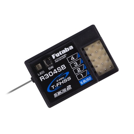
Futaba R304SB T-FHSS 4k receiver

Express delivery

Large selection of carriers

Satisfaction guarantee
Four-channel receiver Futaba of the T-FHSS Surface 2.4GHz transmission system with telemetry for RC cars and boats. It is intended for general use in models of all categories. The S.BUS2 port for bidirectional communication allows the connection of Futaba and S.BUS2 telemetry sensors servos and gyroscopes. The operating states of the receiver are indicated by an LED indicator.
Transmission system
Futaba T-FHSS Surface 2.4GHz (Normal and High Speed modes with very fast response) (automatic detection when the receiver is turned on according to the signal from the transmitter with which the receiver is paired). The "Normal" mode allows the use of any servos (analogue or digital) or RC devices, as the repetition period of the servo signals is 15 ms (repetition frequency 66.7 Hz). "High Speed" mode can only be used by digital servos and most other devices, such as speed controllers for AC motors. The repetition period of the servo signals is 3.3 ms (repetition frequency 303 Hz).
The receiver is not compatible with T-FHSS Air-2.4GHz transmitters for flying models.
Power supply
4.8-7.4 V (nominal voltage) - ie eg 4-6 cells NiMH, 2S LiPo, LiFe, Li-ion, BEC power stabilizers in the given voltage range.
Antenna
The receiver is equipped with a simple antenna.
Receiver outputs, channel modes
The receiver is equipped with sockets for standard Futaba connectors (with protrusion), into which it is of course possible to insert UNI connectors (= JR / Graupner, Hitec) without a side protrusion.
Channel outputs (PWM): The R304SB offers 4 classic PWM channels.
S.BUS2: The S.BUS2 socket allows the connection of Futaba telemetry sensors, the data of which can be displayed on the transmitter and S.BUS2 servos or gyroscopes.
Telemetry
The R304SB transmits the receiver supply voltage data to the transmitter without the need to connect any sensors / p>
The R304SB allows the use of Futaba telemetry sensors and other sensors compatible with the S.BUS2 bus system with bidirectional communication (usable sensors are determined by the transmitter's capabilities).
The receiver set contains: R304SB receiver, operating instructions.
What Is S.BUS2 / S.BUS
- S.BUS - Futaba serial bus with one-way communication enabling control of servos, controllers, switches, gyroscopes and other compatible RC devices connected to a single output port of the S.BUS receiver.
- S.BUS2 - Futaba serial bus for bidirectional communication enabling (as S.BUS) control of servos, controllers, switches, gyroscopes and other compatible RC devices connected to a single output / input port of the S.BUS2 receiver. In addition, it allows the connection of telemetry sensors and the transmission of data from them via a receiver for display on the transmitter; from some S.BUS2 servos can transmit information about the operating current, temperature or angle of the servo output lever to the transmitter.
Unlike conventional RC S.BUS (2) kits, the system uses serial data communication to transmit control signals from the receiver to a servo, gyro or other device. This data contains commands such as "move servo channel 3 to 15 degrees, move servo channel 5 to 30 degrees" for multiple devices. S.BUS (2) devices only execute commands corresponding to their own set channel. For this reason, it is possible to connect several servos to the same signal cable, while setting and controlling them individually as needed. The servo identification code (ID) is used for this. You can find the ID on the sticker on the servo box.
The S.BUS2 servo can be connected to both S.BUS2 and S.BUS ports of the receiver. Its function is given by setting the channel in the servo memory (it is performed using the programming interface of the Futaba transmitter, SBC-1 programmer or USB interface CIU-3 with PC program S-Link - for some servos the channel can be set only with the transmitter). / p>
The S.BUS or S.BUS2 servo connected to the channel output of the classic receiver (PWM) works like a classic servo. Its movement is given by a signal in the channel of the receiver to which it is connected. The settings of the programmable servo functions remain valid.


